MSP430 robotic arm
Move the small arm in your hand, and the big arm on the table moves the same way. The small arm is a replica with a potentiometer in each joint. A microcontroller reads the four potentiometers, turns each reading into a servo position and sends it to a servo driver board, which moves the joints of the big arm. A push button opens the gripper. The firmware is plain C on a 16-bit MSP430, written register by register without an operating system or a hardware abstraction library.
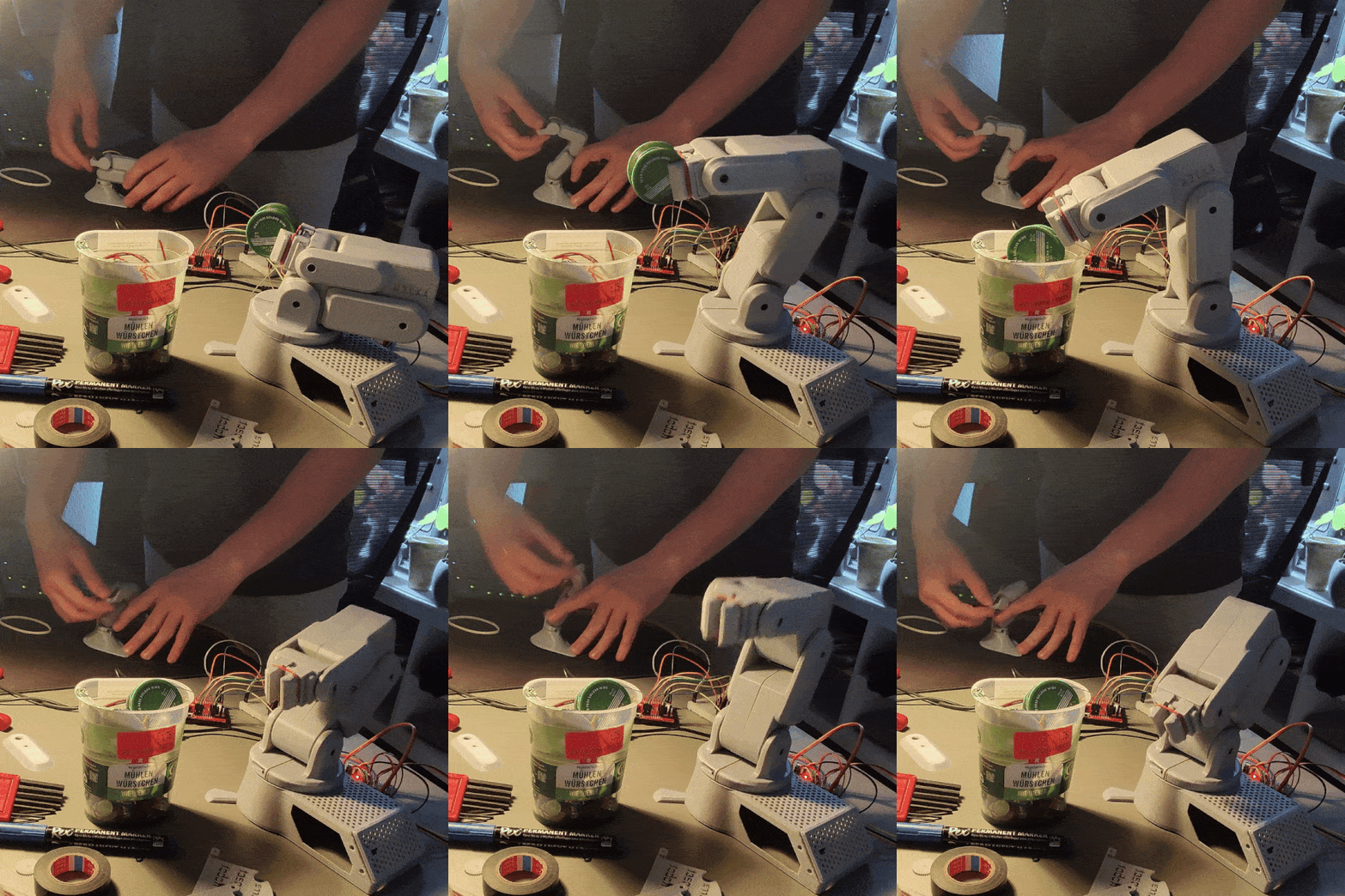 Fig. 1: The arm picks up a roll of tape and drops it into the cup, following the replica in the background
The idea: a joystick shaped like the arm
Controlling a multi-joint arm with buttons or a normal joystick is awkward. You have to think about each joint separately. A replica avoids that: you hold a small copy of the arm and simply put it into the pose you want. Each of its joints turns a potentiometer, so every joint angle of the replica becomes a voltage. The firmware only has to map each voltage to the angle of the matching servo. There is no kinematics involved, no calculation of where the gripper ends up in space. Joint angle goes to joint angle, and the geometry takes care of itself, because both arms are built the same way.
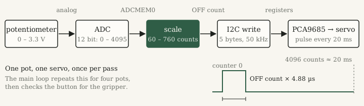 Fig. 2: The path of one reading, from the potentiometer to the servo pulse
Hardware
| Part | Role | Connection |
|---|---|---|
| MSP430FR2355 LaunchPad | microcontroller, 16-bit, about 1 MHz | |
| 4 potentiometers | joint angles of the replica | ADC inputs A1, A4, A5, A6 (P1.1, P1.4, P1.5, P1.6) |
| PCA9685 | 16-channel PWM driver for the servos | I2C at address 0x40 (P1.2 SDA, P1.3 SCL) |
| 5 servos | four joints and the gripper | PCA9685 channels 0, 4, 8, 11 and 3 |
| push button | opens the gripper while pressed | P1.7, internal pull-up |
| LED | shows the gripper state | P1.0 |
The potentiometers are wired as voltage dividers between ground and 3.3 V, so the wiper voltage is proportional to the joint angle. The PCA9685 takes over the timing of all servo pulses. The microcontroller only has to tell it, once in a while, how long each pulse should be.
Step 1: reading a joint angle with the ADC
The MSP430FR2355 has one 12-bit analog-to-digital converter (ADC) with several inputs in front of it. A conversion turns the voltage on the selected input into a number between 0 and 4095:
Because there is only one converter, the firmware reads the four potentiometers one after another. For each one it disables the ADC, selects the input, starts the conversion and goes to sleep:
ADCCTL0 &= ~ADCENC;                 // the input can only change while disabled
ADCMCTL0 = ADCINCH_5;               // select A5
ADCCTL0 |= ADCENC | ADCSC;          // enable and start the conversion
__bis_SR_register(LPM0_bits | GIE); // sleep until the ADC interrupt
When the conversion is done, the ADC interrupt service routine (ISR) runs. It checks which input is selected, stores the result in the matching global variable and wakes the CPU on exit. The main loop then continues right after the line that put it to sleep.
Step 2: from ADC value to servo pulse
A hobby servo does not take an angle. It takes a pulse every 20 ms, and the width of the pulse sets the angle. A typical servo is specified for about 0.5 ms at one end and 2.5 ms at the other, with 1.5 ms in the middle.
The PCA9685 generates these pulses with a 12-bit counter per period. It divides its internal 25 MHz oscillator by a prescaler and counts from 0 to 4095 again and again. For 50 Hz the datasheet1 gives
so one count lasts and one period . Each channel has an ON and an OFF register. The output goes high when the counter reaches ON and low when it reaches OFF. With ON fixed at 0, the OFF value alone sets the pulse width:
The firmware maps the ADC value linearly onto the OFF count. It also flips the direction with , so that a joint of the replica and the matching servo turn the same way:
uint16_t servo_position2 = ((uint32_t)(4095 - ADC_Result_2) * 700) / 4095 + 60;
set_servo_position(4, servo_position2);
The cast to uint32_t matters. On the MSP430, int is only 16 bits wide, and
is far beyond the 65,535 an unsigned 16-bit number can hold.
Without the cast, the product would wrap around.
The OFF count runs from 60 to 760. One count of the PCA9685 corresponds to about 5.9 steps of the ADC, so small noise on the potentiometer rarely reaches the servo.
| Pot position | ADC | OFF count | Pulse |
|---|---|---|---|
| one end | 4095 | 60 | 0.29 ms |
| middle | 2048 | 409 | 2.00 ms |
| other end | 0 | 760 | 3.71 ms |
| gripper closed | 210 | 1.02 ms | |
| gripper open | 350 | 1.71 ms |
Step 3: writing the registers over I2C
The PCA9685 sits on the I2C bus at address 0x40. Each channel has four registers in a
row, starting at 0x06 for channel 0: ON low byte, ON high byte, OFF low byte, OFF high
byte. With the auto-increment bit set in the MODE1 register, one write fills all four:
the first data byte is the start register, the next four bytes land in consecutive
registers.
#define LED_ON_L(channel)  (LED0_ON_L + 4 * (channel))

void set_servo_position(uint8_t channel, uint16_t position) {
    if (channel > 15) return;
    char servo_data[] = {LED_ON_L(channel), 0x00, 0x00, (position & 0xFF), (position >> 8)};
    write_I2C(servo_data, 5);
    LPM0;                                   // sleep until the STOP interrupt
}
The transfer itself is interrupt-driven. The eUSCI_B0 module runs as I2C master at about
50 kHz, the 1 MHz system clock divided by 20. write_I2C stores a pointer to the bytes,
loads the byte counter and sends a START. Every time the transmit buffer is empty, the
I2C ISR puts the next byte in. When the counter reaches zero, the hardware sends the STOP
by itself (automatic STOP mode), and the STOP interrupt wakes the CPU. Six bytes on the wire
(address and five data bytes) at nine clock cycles each take about 1.1 ms. During that
time the CPU is switched off.
Before the main loop starts, the firmware configures the PCA9685 with two writes. It
writes the prescaler 121 to register 0xFE, which is only possible while the chip is in
sleep mode, as it is after power-up. Then it writes 0x21 to MODE1. That clears the sleep
bit so the oscillator starts, and sets the auto-increment bit used above.
The main loop
Put together, the firmware is one loop without any waiting time of its own:
- Read potentiometer A1, compute the OFF count, write channel 0.
- Read A5, write channel 4.
- Read A4, write channel 8.
- Read A6, write channel 11.
- If the button is pressed and the LED is off, switch the LED on and open the gripper (channel 3 to 350). If it is released and the LED is on, switch the LED off and close the gripper (210). The LED doubles as a memory of the gripper state, so the gripper is only written when the button changes.
Every wait in between is spent in low-power mode 0 (LPM0). In LPM0 the CPU is stopped, but the clock for the peripherals keeps running, so the ADC and the I2C module work on while the CPU sleeps. One pass takes about 5 ms, most of it the four I2C writes, so the arm follows the replica without visible delay.
The demo computes the same numbers as the firmware: the scaling formula, the PCA9685 timing and the exact I2C bytes. The arm drawing assumes a servo that is specified for 0.5 to 2.5 ms over 180°, and the assignment of joints to channels is illustrative, since the repository does not document it.
Results
The arm follows the replica smoothly, and with a bit of practice it can pick up small objects and drop them somewhere else (Fig. 1). The firmware is about 300 lines in a single file. It was written a few weeks before the pill sorting machine, whose I2C driver uses the same approach: interrupt-driven, automatic STOP, and the CPU asleep while the bytes go out.
Footnotes
-
NXP, PCA9685: 16-channel, 12-bit PWM Fm+ I2C-bus LED controller, product data sheet, description of the PRE_SCALE register. ↩