Pill sorting machine
Put a pill on the platform, and the machine works out its colour, turns towards the matching bin and tips the pill in. Red, green and blue pills each end up in their own compartment, and the display keeps count. We built it as a team of three in the Embedded Systems and Robotics course at Reutlingen University. The firmware is plain C on a 16-bit MSP430 microcontroller, written without an operating system or a hardware abstraction library, register by register.
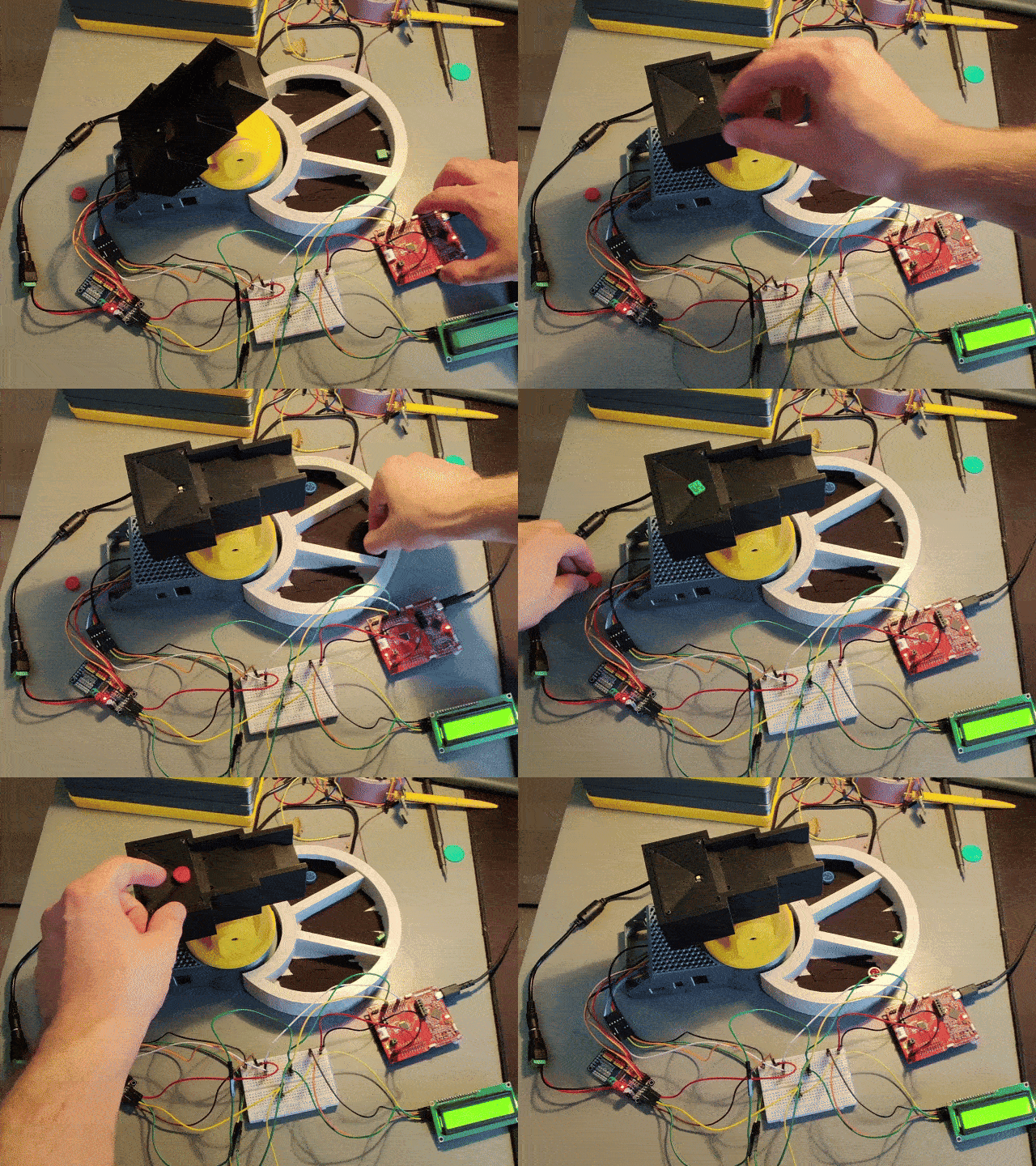 Fig. 1: A pill is detected, classified as red and tipped into the red bin
How a pill gets sorted
- Detect. The colour sensor looks at the empty platform and remembers how bright it is. A pill casts a shadow on the sensor, and the measured brightness drops.
- Measure. The sensor switches on its white LED and measures the red, green and blue light reflected by the pill.
- Classify. If one colour clearly dominates the other two, the pill gets that colour. Otherwise it is left where it is.
- Sort. The direction servo turns the platform towards the bin for that colour. The tilt servo then tips the platform and the pill slides off.
- Report. The LCD shows the detected colour and the updated counters, and two LEDs show whether the machine is ready or busy.
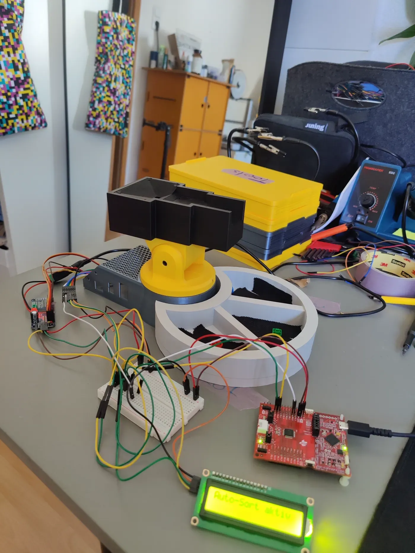 Fig. 2: The complete setup. The platform sits on a servo tower above a ring with three bins. The MSP430 board is on the right, the LCD in front.
Hardware
| Part | Role | Connection |
|---|---|---|
| MSP430FR2355 LaunchPad | microcontroller, 16-bit, 1 MHz | |
| TCS34725 | RGB colour sensor with white LED | I2C, address 0x29 |
| PCA9685 | 16-channel PWM driver for the two servos | I2C, address 0x40 |
| LCD1602 | 2 × 16 character display with I2C adapter | I2C, address 0x3F |
| 2 servos | turn the platform and tilt it | PWM from the PCA9685 |
| 2 buttons, 2 LEDs | user input and status | GPIO |
All three peripherals share one I2C bus, so the microcontroller needs only two pins for everything except buttons and LEDs. The logic runs at 3.3 V. The servos get a separate 5 V supply, so that the current they draw when they start moving does not disturb the microcontroller.
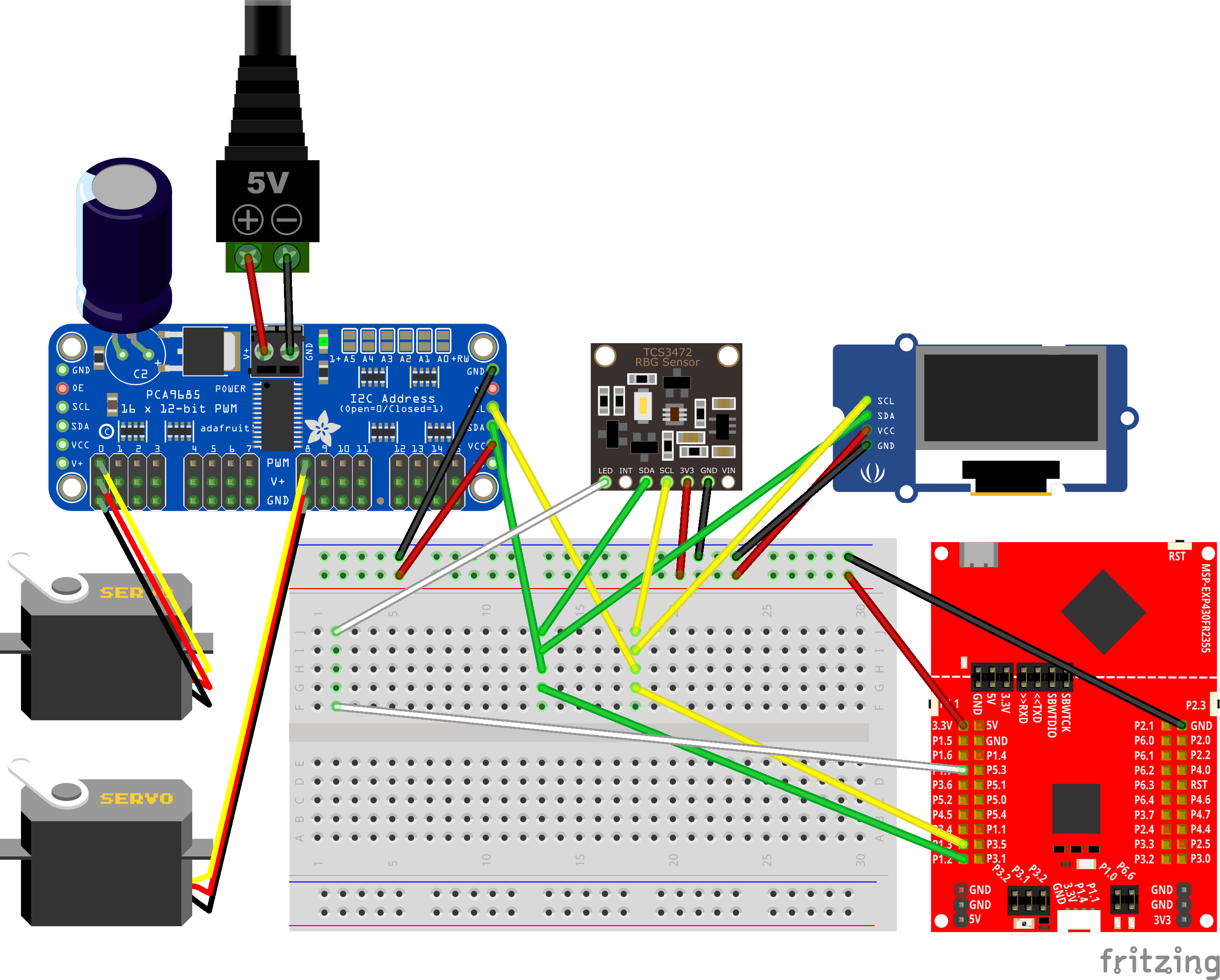 Fig. 3: Wiring diagram
Firmware architecture: sleep until something happens
The machine spends almost all of its time waiting: for a button, for a pill, for a timer.
The firmware is therefore built around events and low power. Interrupt service routines
(ISRs) do almost nothing themselves. They set a bit in a global eventBits variable and
wake the CPU. The main loop takes the pending events one at a time, hands each to the state
machine, and puts the CPU back into low-power mode 3 (LPM3) once nothing is left. In LPM3
the CPU is stopped and draws almost no current, while the timers keep running on a
32.768 kHz clock.
while (true)
{
event = get_event(&eventBits); // highest pending bit, cleared on read
while (event > EVT_NO_EVENT)
{
handle_event_FSM(¤tState, event);
event = get_event(&eventBits);
}
LPM3; // sleep until the next interrupt
}Each event is one bit, and get_event scans from the highest bit down. The bit position
is therefore also the priority. If a timeout and a button press arrive together, the
timeout is handled first.
| Bit | Event | Set by |
|---|---|---|
| 4 | DEACTIVATION_PER_TIMER | Timer B3, after 12 s without activity |
| 3 | OBJECT_DETECTED | the object check, when the brightness drops |
| 2 | S2 | button S2 (port interrupt) |
| 1 | S1 | button S1 (port interrupt) |
| 0 | SYSTEM_TICK | Timer B0, once per second in auto mode |
Four hardware timers, all clocked from the 32.768 kHz clock, cover the time-based parts: the 1 s system tick (B0), blocking delays during which the CPU still sleeps (B1), a 500 ms debounce window for the buttons (B2), and the inactivity timeout (B3). For debouncing, the button ISR disables both button interrupts and starts Timer B2. Its ISR enables them again 500 ms later, so the bouncing contacts cannot trigger a second press.
The state machine
All behaviour lives in one state machine with five states. Every state reacts to every
event, often by ignoring it. Writing it out as a nested switch over state and event makes
it easy to check that no combination is forgotten.
The demo runs the same logic as the firmware: the same events and priorities, the same transitions, the original display texts, colour thresholds and servo angles. Only the sensor readings are example values.
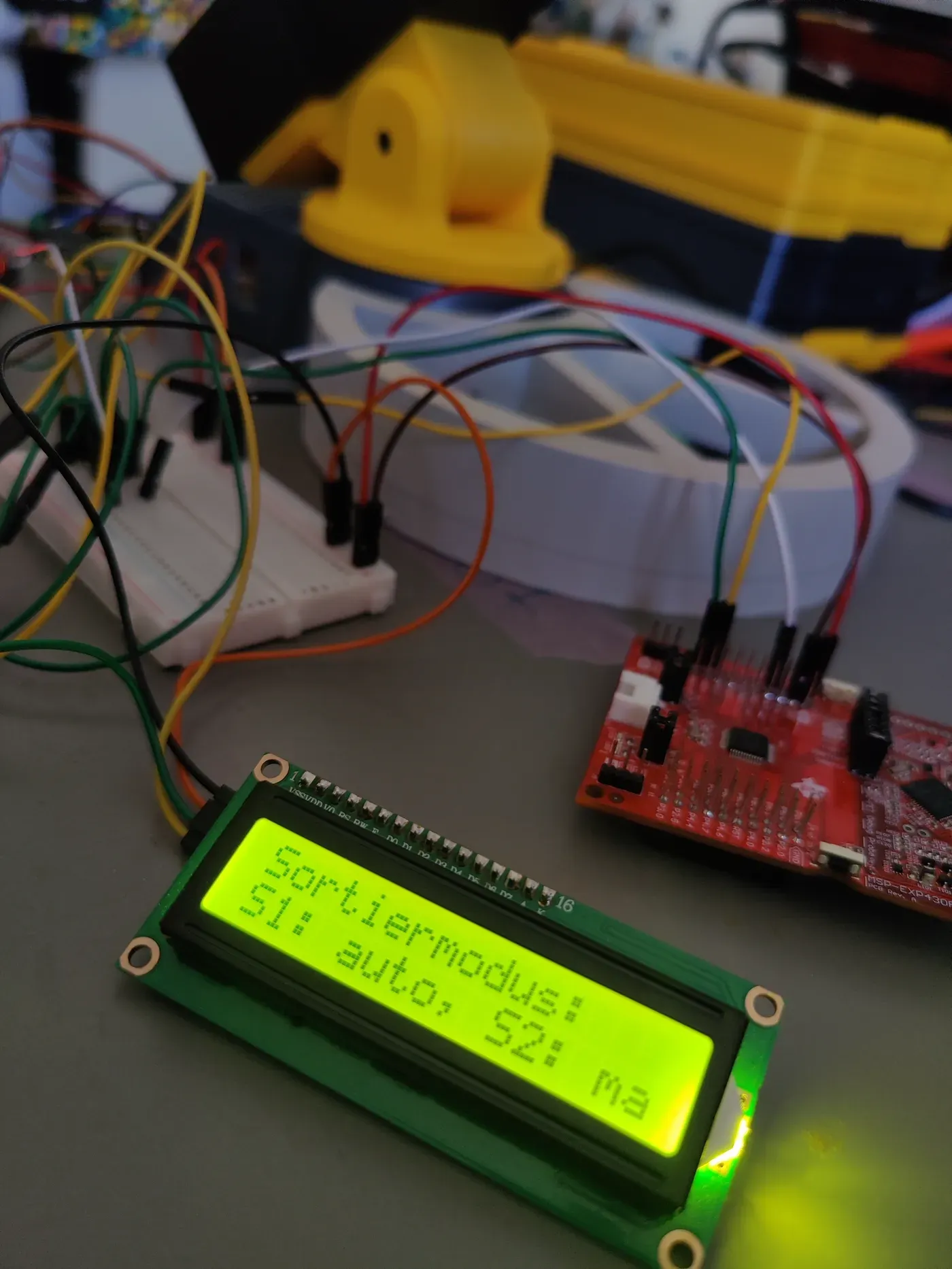 Fig. 4: The mode selection on the real display, “S1: auto, S2: manual”
Seeing colour
The TCS34725 measures four channels: red, green, blue and an unfiltered clear channel for overall brightness. Each measurement integrates light for about 100 ms, set as 42 integration cycles of 2.4 ms. To save power, the firmware switches the sensor on for each measurement and off again afterwards.
Is there a pill? When a sorting mode starts, the firmware reads the clear channel of the empty platform as a reference. A pill shades the sensor. If the clear value falls more than 40 % below the reference, a pill is present. No extra light barrier is needed.
Which colour is it? With the LED on, the firmware reads the three colour channels and scales them down to 8 bits. It halves all three together until the largest fits into 0 to 255, so the ratios between them stay the same. Then a colour counts as detected if it is at least 1.4 times as strong as both others, above 100 itself, and both others are below 100. For red:
The factor 1.4 appears as , because the MSP430 has no floating-point unit. Integer comparisons cost a few cycles, while a software floating-point multiplication would cost hundreds.
if (red * 10 > green * 14 && red * 10 > blue * 14 &&
    green < 100 && blue < 100 && red > 100)
{
    plattform_empty_r();               // turn to the red bin and tip
    display_detected_color(RED);
    redSorted++;
}
Moving the pill
Hobby servos expect a pulse every 20 ms, i.e. at 50 Hz, and the width of the pulse sets the angle. The PCA9685 generates these pulses for us. It divides its 25 MHz clock into 4096 steps per period:
One step is then , and each angle becomes a number of steps:
| Angle | Steps | Pulse | Used for |
|---|---|---|---|
| 40° | 240 | 1.17 ms | tilt: tip the pill off |
| 50° | 265 | 1.29 ms | direction: red bin |
| 90° | 365 | 1.78 ms | direction: green bin, tilt: level |
| 120° | 440 | 2.15 ms | direction: blue bin |
| 135° | 477 | 2.33 ms | tilt: folded away while switched off |
A sort turns the platform to the bin, waits 0.7 s, tilts to 40°, waits 1.5 s for the pill to slide off, and returns to the level position.
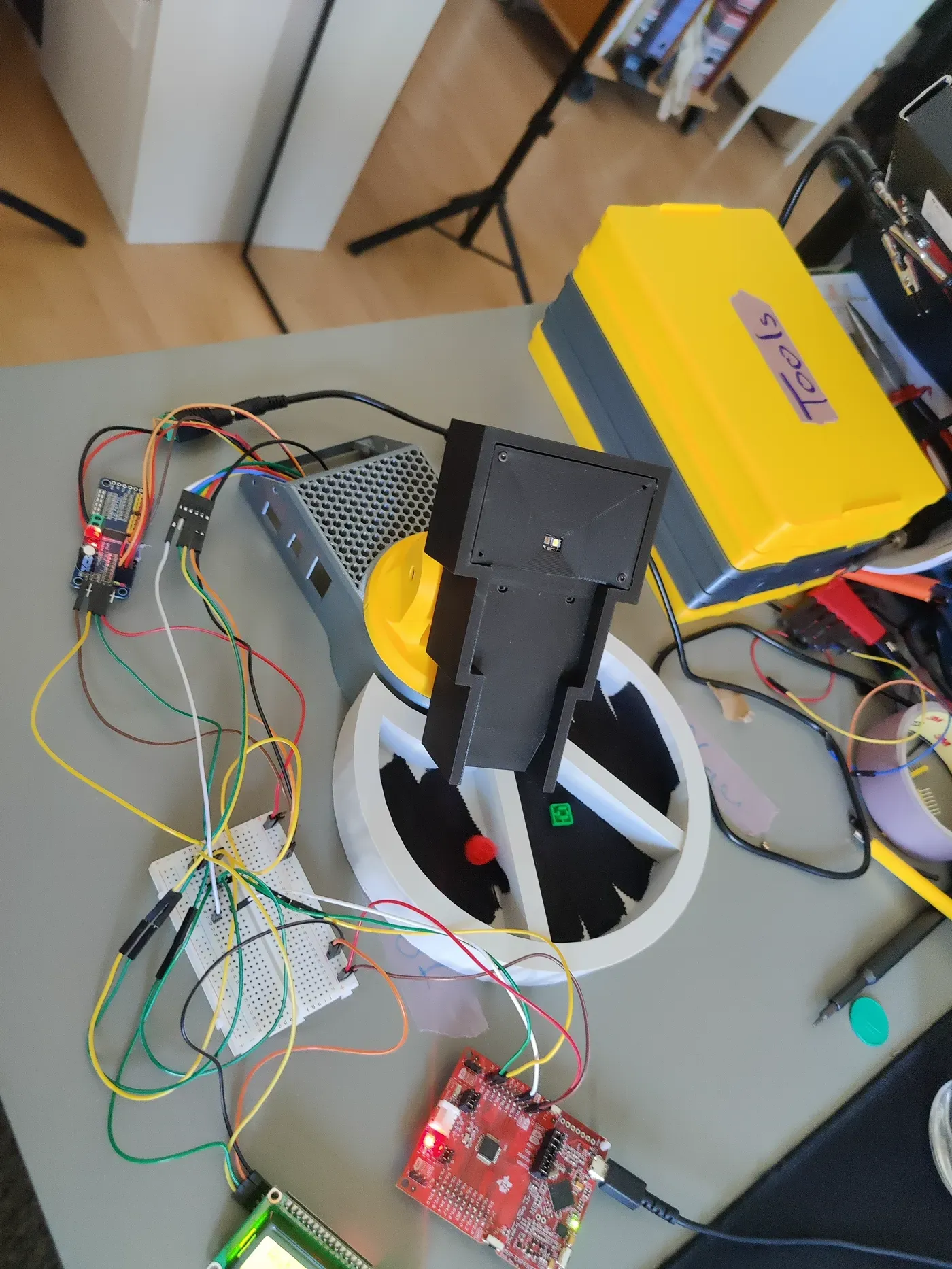 Fig. 5: The platform over the ring of bins, with a red pill on it
I2C, interrupt-driven
All three devices are driven by the eUSCI_B0 module as I2C master at 50 kHz (the 1 MHz system clock divided by 20). Transfers are interrupt-driven: the code loads the number of bytes, sends a START and goes to sleep in LPM3. The ISR feeds the transmit buffer byte by byte, the hardware sends the STOP automatically when the byte counter reaches zero, and the STOP interrupt wakes the CPU again. A NACK, i.e. a device that does not answer, wakes it as well instead of hanging forever.