Software rendering pipeline
Every game and every 3D viewer runs the same pipeline: take triangles in 3D, decide where they land on the screen, decide which ones are visible and give them a colour. On a GPU most of this disappears behind a single draw call. This project does it by hand in Java, with no OpenGL and no scene graph. It reads an OBJ mesh, moves every triangle through a virtual camera, projects it onto the screen and fills the resulting polygons on a Swing panel.
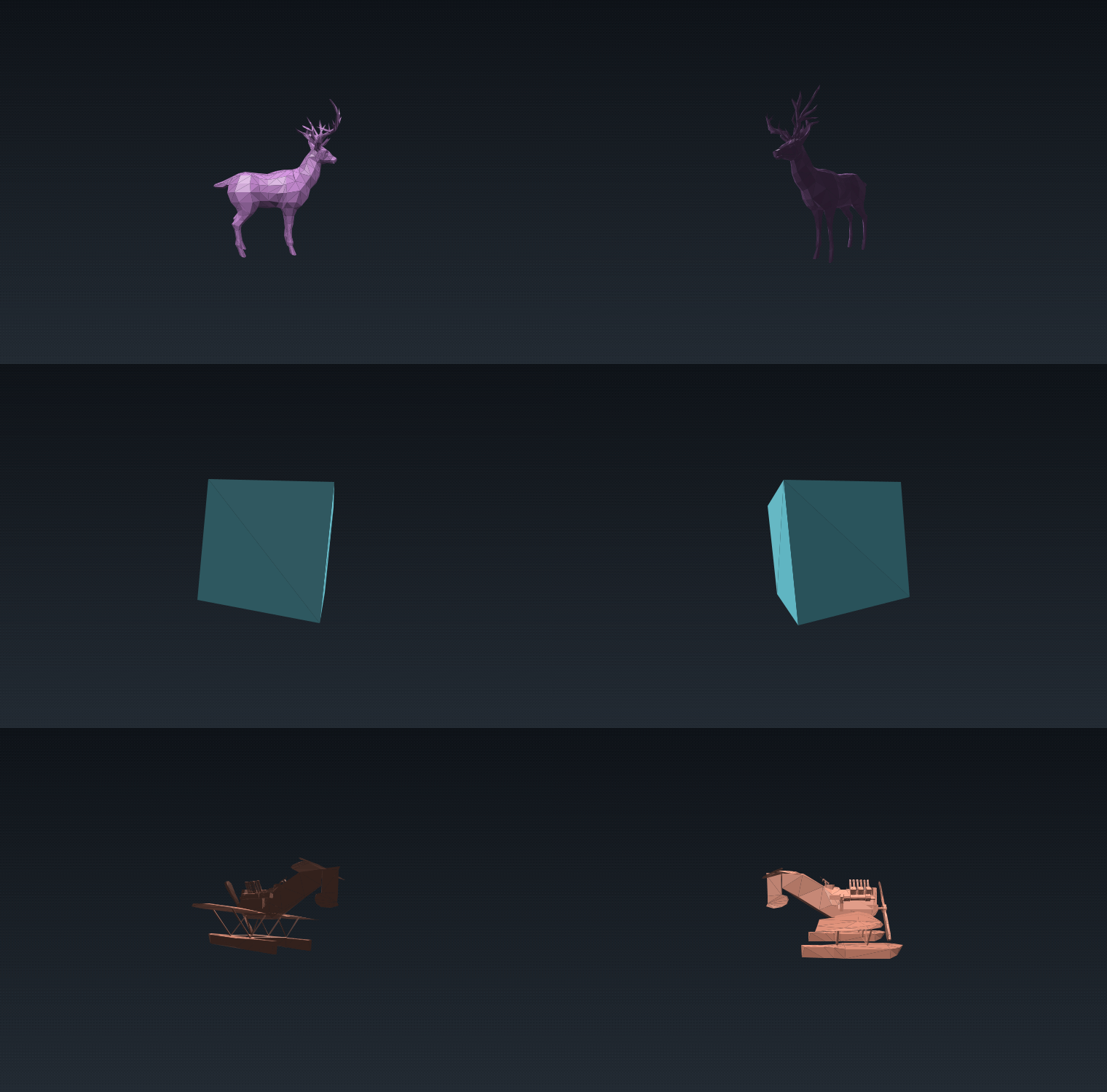 Fig. 1: The three bundled models, rendered entirely in software
The idea: a chain of coordinate systems
A vertex is not drawn in one jump. It is described in a sequence of coordinate systems, and each step to the next one is a matrix multiplication or a division:
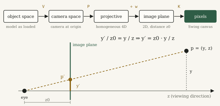 Fig. 2: Top, the coordinate spaces a vertex passes through. Bottom, the perspective projection seen from the side.
| Space | What the coordinates mean | How to get there |
|---|---|---|
| Object space | positions as stored in the OBJ file | load and normalize the mesh |
| Camera space | positions relative to the camera, which looks along | view matrix |
| Projective space | homogeneous 4D coordinates | projection matrix |
| Image plane | 2D positions on a plane at distance | divide by |
| Pixel space | column and row on the Swing canvas | camera intrinsics |
Because the view, projection and intrinsics steps are all matrices, they can be multiplied into one matrix once per frame, . Every vertex then costs one matrix-vector product and one division.
Interactive demo
The demo below is a JavaScript port of the renderer with the same math: same camera, same projection, same culling test and the same painter’s algorithm, on procedurally generated meshes instead of the OBJ files.
1. Loading the mesh
An OBJ file is plain text. v x y z lines list the vertices and f i j k lines list the
triangles as indices into that vertex list. The reader builds an indexed triangle mesh
from them and drops degenerate triangles with almost zero area. The deer has 772 vertices
and 1,503 triangles, the cube 8 and 12.
The three OBJ files come at very different scales, so after loading, every mesh is centred on its bounding box and scaled so that its largest side has a fixed length. One camera setup then works for all of them.
2. The camera and the view matrix
The camera is defined by three vectors: the eye position, the point ref it looks at
and an up direction. From these the renderer builds an orthonormal camera frame:
Put as columns next to the eye position, these vectors form the matrix that maps camera coordinates into the world. The view matrix is its inverse. It moves the world so that the camera sits at the origin and looks along :
Matrix4f cameraToWorld = new Matrix4f(
        x.x, y.x, z.x, eye.x,
        x.y, y.y, z.y, eye.y,
        x.z, y.z, z.z, eye.z,
        0,   0,   0,   1);
Matrix4f view = cameraToWorld.invert();
The controls never touch the mesh. Dragging rotates eye around ref, the mouse wheel
changes their distance, and Alt + drag moves both together to pan. The view matrix is
rebuilt on every repaint, so the whole mesh goes through the pipeline again each frame.
3. Backface culling
On a closed mesh, the triangles facing away from the camera are always hidden behind the front ones. Culling skips them before any further work. A triangle faces the camera if its normal points towards it. In camera space the camera is at the origin, so the vector from a vertex to the camera is simply :
This only works if all triangles are wound the same way, so that the cross product gives the outward normal. The Show normals option in the Java app and in the demo draws these normals, which is the quickest way to check the winding of a model.
4. Perspective projection
Distant objects look smaller. The side view in Fig. 2 shows why: a point at height and depth is seen along a ray through the eye, and that ray hits the image plane at distance at height . Two similar triangles, nothing more.
A division by is not a linear map, so it cannot be a matrix on its own. Homogeneous coordinates solve this. The projection matrix copies into the fourth coordinate , and the division happens afterwards:
The intrinsics matrix turns image-plane coordinates into pixels. It scales by the focal length , derived from the horizontal field of view, flips because screen rows grow downwards, and moves the origin to the centre of the canvas:
Triangles with a vertex behind the camera () are skipped, since dividing by a negative depth would flip them across the screen.
5. Visibility: the painter’s algorithm
After projection, several triangles can cover the same pixel, and the nearest one has to
win. GPUs solve this per pixel with a depth buffer. Swing only offers fillPolygon,
so the renderer uses the painter’s algorithm instead: compute one depth per triangle,
the mean of its three vertices in camera space, sort from far to near and paint in
that order, so that closer triangles cover the ones behind them.
triangles.sort(Comparator.comparing(RenderTriangle::depth).reversed());
for (RenderTriangle t : triangles) {
    g2.setColor(t.color());
    g2.fillPolygon(t.polygon());
}
This is cheap and works well for the bundled models. It fails when one depth value per triangle is not enough: when triangles intersect, as in the two-boxes demo, or when three triangles overlap each other in a cycle. No ordering of whole triangles is correct in those cases. A depth buffer has no such problem, because it decides per pixel.
6. Shading
Each triangle gets a single colour from its face normal and a few fixed lights:
- a key light that defines the shape, ,
- a weaker fill light so that the shadow side does not go black,
- a rim term that brightens faces seen at a grazing angle,
- a Blinn-Phong highlight, with the half vector between the light and the view direction.
The shininess and the highlight strength are set per model, so the cube looks glossy and the deer matte. None of this is physically based. It is just enough shading to make the 3D shape readable. Because the colour is constant per triangle, the facets stay visible. That is flat shading.
The background is a dark gradient with a 4 × 4 Bayer dither pattern added, so that the GIF export does not show colour bands.