Raydar
A single camera sees the world flat. If a small dot moves across its image, the camera knows the direction the dot is in, but not how far away it is: a bird at 50 m and a plane at 1000 m can land on the same pixel. Put a second camera somewhere else, and the same object appears in a different direction. Only one point in space lies in both directions at once. Finding that point is called triangulation.
Raydar is a small C++ library that does this for moving objects. It reads synchronised image sequences from several calibrated cameras, finds what moved, turns every moving blob into a ray in 3D, and lets the rays vote in a shared voxel grid. Where rays from several cameras pass through the same voxel, there is an object. The output is a list of 3D positions per frame. I built it together with Ben Wehrberger over the summer of 2025, and wrote up the results in December.
To test it without real hardware, the input comes from Blender: a plane flies over a ring of virtual cameras that look up into the sky.
 Fig. 1: The synthetic test scene. A plane at 1000 m altitude flies over cameras placed on the ground.
The pipeline at a glance
For every camera, and for every pair of consecutive frames:
- Find motion. Compare the two images pixel by pixel and keep the pixels that changed.
- Group pixels. Join neighbouring changed pixels into blobs and take each blob’s centre.
- Cast rays. Turn each blob centre into a ray in world coordinates, using the camera’s position, rotation and field of view.
Then, for every frame, with the rays of all cameras together:
- Vote in a voxel grid. Walk each ray through a grid of 1 m cubes and count how many rays pass through each cube.
- Read off detections. Cubes with enough rays are where the object is.
The sections below go through these steps one by one. The demo after step 5 lets you play with the whole chain in 2D.
Step 1: what moved?
The simplest motion detector is a frame difference. If is the brightness of pixel in frame , a pixel counts as moving when
The example program uses on a brightness scale of 0 to 255. That is very sensitive, which is fine for clean rendered images. Real cameras have sensor noise and would need a much larger threshold.
float change = curr_pixel - prev_pixel;
if (abs(change) > motion_threshold) {
    PixelChange current_pixel{x, y, change};
    // skip pixels that were already reported for the previous frame pair
    if (prev_detection_set.find(current_pixel) == prev_detection_set.end()) {
        pixels_with_motion.push_back(current_pixel);
    }
}
A frame difference has one well-known side effect. When an object moves, pixels change in two places: where it arrives (background turns into object) and where it left (object turns into background). The detector reports both, so a fast object shows up as two blobs, one at the old and one at the new position. The check against the previous detection in the snippet above removes pixels that were already reported one step earlier, which suppresses some but not all of these duplicates.
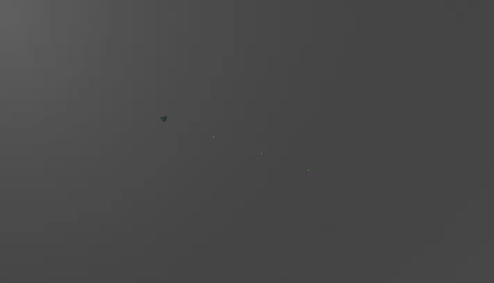 Fig. 2: One camera’s image with the blob centres of all frames drawn in. The small dots to the right of the plane trace its path across the image.
Step 2: from pixels to blobs
The object covers many pixels, but one ray per object is enough. find_object_centers
groups the moving pixels with a flood fill: start at any moving pixel, add all moving
pixels in its neighbourhood, then theirs, until no new ones are found. The blob centre is
the average pixel position:
The neighbourhood is pixels instead of the usual . A plane seen from far away is thin, and a frame difference often leaves small gaps inside it. The larger neighbourhood bridges those gaps so that one plane does not split into several blobs. The price is that two different objects whose pixels come within two pixels of each other merge into one.
Step 3: from a pixel to a ray
Now the camera model comes in. Every frame in the input comes with a JSON entry that holds the camera’s position, its rotation as three Euler angles and its horizontal field of view :
{
  "camera_index": 0,
  "frame_index": 1,
  "camera_rotation": { "X": 89.99, "Y": 149.99, "Z": 0.0 },
  "fov_degrees": 112.62,
  "image_file": "camera0_frame0001.png",
  "camera_position": { "X": 75.0, "Y": 0.0, "Z": 2.0 }
}
The camera is treated as a pinhole camera. In its own coordinate system it sits at the origin and looks along , with an image plane at distance 1. A pixel in an image of pixels lies on that plane at
The moves to the centre of the pixel. The first factor maps the pixel column to , and scales that to the true width of the image plane at distance 1. The axis is flipped because image rows count downwards. This direction is then rotated into the world with the camera’s rotation , the same XYZ Euler order that Blender uses:
where is the camera position. In code:
float camera_x = (2.0f * (pixel_x + 0.5f) / img_width - 1.0f) * tan_half_horizontal_fov;
float camera_y =
    (1.0f - 2.0f * (pixel_y + 0.5f) / img_height) * tan_half_horizontal_fov * aspect_ratio;
float camera_z = -1.0f;

Eigen::Vector3f local_dir(camera_x, camera_y, camera_z);
local_dir.normalize();
Eigen::Vector3f world_dir = apply_rotation(local_dir, info.camera_rotation);
Getting the rotation order right was one of the fixes in the history (fix: apply_rotation order from zyx to xyz). With the wrong order every ray still looks plausible on its own,
it just points somewhere else, and the rays of different cameras no longer meet at the object.
Step 4: letting the rays vote
Two lines in 3D almost never intersect exactly. Pixel quantisation alone moves each ray a little, so two rays aimed at the same plane pass each other at some small distance. One option is to compute their closest point analytically. Raydar takes a more robust route that also works for many rays and many objects at once: it divides space into voxels of m and counts, for each voxel, how many rays pass through it.
The grid covers the camera positions plus 1000 m in every direction. Storing it densely would be wasteful, because almost all voxels stay empty. Raydar therefore uses a sparse grid, a hash map from voxel index to a counter. Only voxels that a ray actually touches get an entry.
To find the voxels a ray passes through, Raydar uses the voxel traversal of Amanatides and Woo1, the 3D version of drawing a line on a pixel grid. For each axis it keeps , the ray parameter at which the ray crosses the next voxel border on that axis, and , how far has to grow to cross one full voxel of size on that axis. Each step moves into the neighbouring voxel along the axis whose border comes first:
while (t_current < t_exit) {
    grid[std::make_tuple(current_idx[0], current_idx[1], current_idx[2])] += value;

    int axis = 0;
    if (t_max[1] < t_max[axis]) axis = 1;
    if (t_max[2] < t_max[axis]) axis = 2;

    t_current = std::min(t_max[axis], t_exit);
    current_idx[axis] += step[axis];
    t_max[axis] += t_delta[axis];
}
Every voxel the ray touches is visited exactly once, with only additions and comparisons per step. Before the loop, a ray–box test clips the ray to the grid, and the first voxels after the camera are skipped. Close to a camera, all of its rays are still packed together and would vote for the same voxels.
Step 5: reading off detections
After all rays of a frame are in the grid, every voxel whose count reaches the threshold
of counts as a detection, and its centre is written to detected_objects.txt:
A single ray only says “somewhere along this line”, so an object needs at least two cameras to be found. More cameras and a higher threshold make false detections less likely, because a random crossing of two unrelated rays is common, but a voxel where three unrelated rays meet is rare.
The demo below is the same pipeline in a 2D side view. Cameras stand on the ground and look up. Each camera has a one-row image and only reports the pixel where it sees the object. From that pixel it casts a ray, the rays are walked through a grid with the same traversal as above, and cells that pass the detection rule light up.
Results
The test scene has five cameras on a ring of radius 75 m, 2 m above the ground. The capture script uses three of them, at 0°, 72° and 144° around the ring, so the cameras are 88 m and 143 m apart. The plane flies in a straight line at 1000 m altitude.
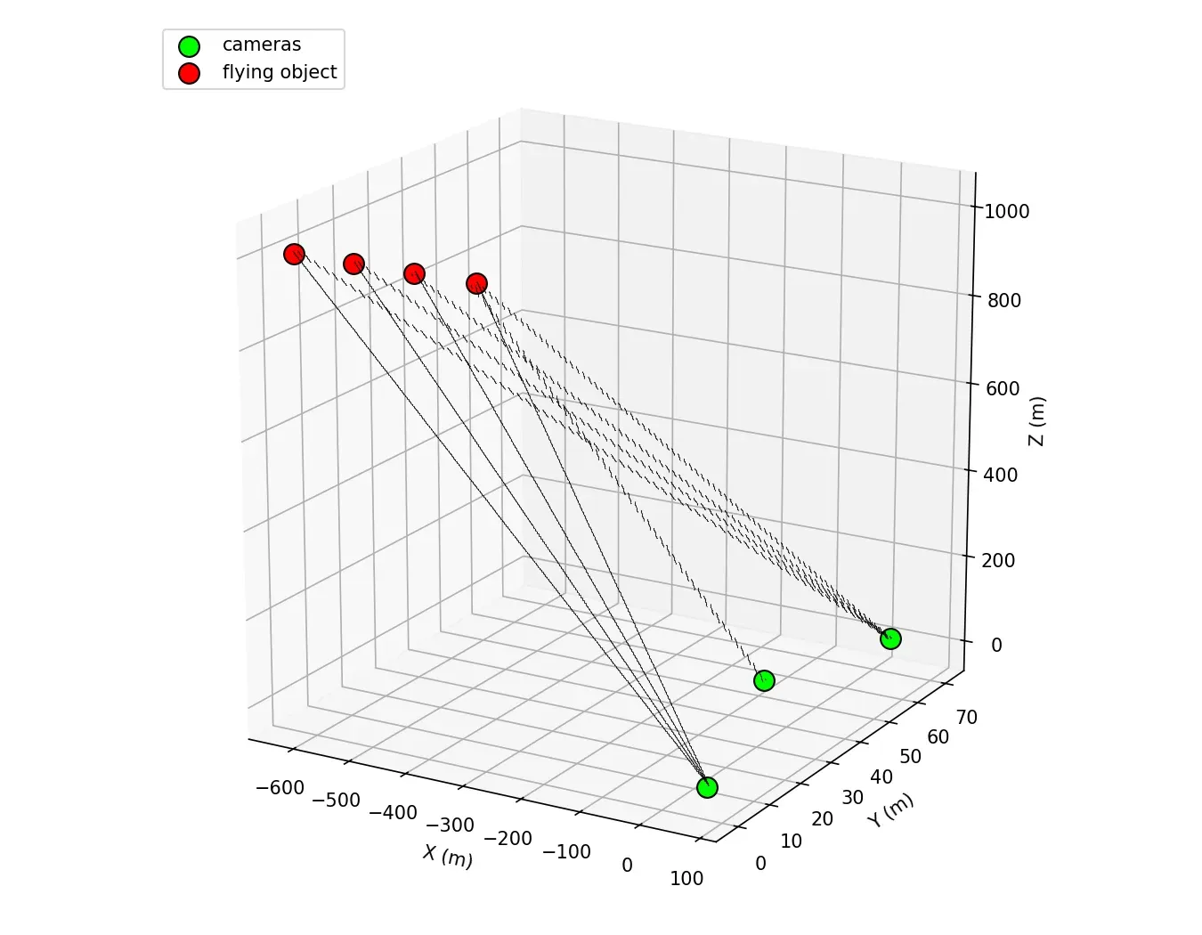 Fig. 3: The three cameras (green) and the four detected positions (red). Each dashed line is one ray from a camera through a blob centre.
The repository’s visualisation script lists the plane’s positions for this run, 105 m apart. Compared with the detections:
| Detected (m) | Plane position (m) | Difference x, y, z (m) |
|---|---|---|
| (−628, 1, 1001) | (−625, 0, 1000) | −3, +1, +1 |
| (−523, 1, 1003) | (−520, 0, 1000) | −3, +1, +3 |
| (−413, 1, 994) | (−415, 0, 1000) | +2, +1, −6 |
| (−306, 0, 987) | (−310, 0, 1000) | +4, 0, −13 |
Sideways () the detections are within one voxel. Along the flight direction () they are a few metres off, which is the size of the plane itself (an F-35 model, 15.7 m long), so it matters where on the plane the blob centre lands. The height () is the least precise, and the reason is geometry, not code. Seen from the plane, two cameras 88 to 143 m apart are only 3.7° to 7.5° apart, so their rays are almost parallel. If each ray has a sideways uncertainty of about one voxel , the region where two such rays overlap is stretched along the viewing direction by about
which for between 3.7° and 7.5° is 8 to 15 voxels. The narrow-spread setting in the demo shows exactly this stripe. Wider camera spacing, or cameras on hills around the area, would fix it far better than smaller voxels.
Footnotes
-
J. Amanatides and A. Woo, A Fast Voxel Traversal Algorithm for Ray Tracing, Eurographics 1987. ↩