Marching cubes
Some shapes are easiest to describe with a single formula. A sphere is every point at distance from its centre, a torus is a circle swept around an axis. A renderer, a game engine or a 3D printer cannot use a formula, though. It needs triangles. Marching cubes (Lorensen and Cline, 1987)1 is the classic algorithm that bridges the two: it turns an implicit function into a triangle mesh. The same algorithm turns CT and MRI scans into 3D models of bones and organs.
This project is a self-contained implementation in Java. One run produces three meshes as OBJ files, ready for Blender or MeshLab.
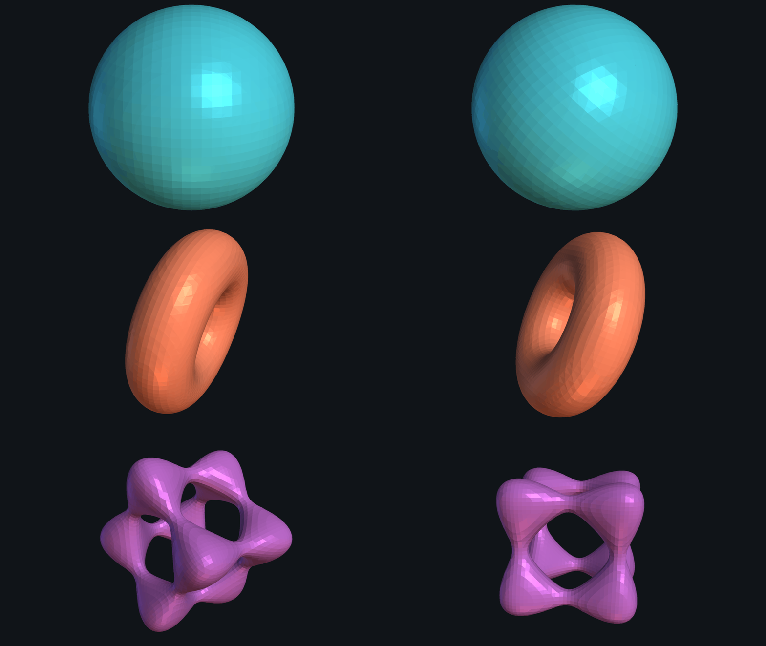 Fig. 1: The three generated meshes, rendered with PyVista
Shapes as formulas
An implicit function assigns a number to every point in space. The surface is the set of points where that number is zero:
By convention inside the shape and outside, so the sign alone says on which side of the surface a point lies. The three shapes in this project:
| Shape | Kind of field | |
|---|---|---|
| Sphere | signed distance: the value is the distance to the surface | |
| Torus | polynomial of degree 4 | |
| Goursat surface | polynomial of degree 4, evaluated at |
The Goursat surface is a rounded cube with holes in its faces, a nice test because its topology is more interesting than a sphere’s. Each shape is one small class behind an interface, so adding a new shape means writing one method:
public interface ImplicitFunction {
    float eval(Vector3f p);
}

public class Sphere implements ImplicitFunction {
    public float eval(Vector3f p) {
        return p.distance(center) - radius;
    }
}
The problem is now clear. We can ask about any point we like, but we have no list of points on the surface, let alone triangles between them.
The idea in 2D: marching squares
Marching cubes is easiest to understand one dimension lower, where it is called marching squares and produces a contour line instead of a surface. The recipe:
- Sample. Lay a grid over the domain and evaluate at every grid corner.
- Classify. For each cell, check which of its 4 corners are inside (). With one bit per corner this gives a number from 0 to 15, the case index.
- Look up. Only the corner pattern decides which edges the contour crosses. A table with 16 entries stores, for every case, which edges to connect.
- Place. Put the line’s endpoints on those edges, then move on to the next cell.
Cells that are completely inside (case 15) or completely outside (case 0) produce nothing. The interesting work only happens in the thin band of cells the contour passes through.
Going to 3D
In 3D the cells are cubes. A cube has 8 corners, so the case index has 8 bits and there are cases. Instead of line segments, each case stores up to 5 triangles, and each triangle is given as three of the cube’s 12 edges.
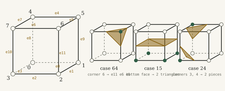 Fig. 2: Left, the numbering of corners and edges used in the code. Right, three entries of the lookup table. Filled corners are the ones whose bit is set, the triangles are what the table returns for that pattern.
The table is stored as one flat array with 15 entries per case, i.e. 5 triangles × 3 edges, with marking the end of the list. Case 64 (only corner 6 set) is a single triangle that cuts that corner off. Case 15 (the four bottom corners set) is a horizontal quad, split into two triangles. Case 24 has two set corners that do not touch, so it produces two separate pieces.
Working out 256 configurations by hand would be tedious and error-prone. Lorensen and Cline reduced them to 15 basic patterns using symmetry: rotating the cube, or swapping inside with outside, does not change which edges the surface crosses. The full table follows from those 15 patterns.
Computing the case index and reading the table takes only a few lines:
int index = 0;
for (int i = 0; i < 8; i++)
    if (values[i] > isoValue) index |= 1 << i;    // one bit per corner

int[] tris = Arrays.copyOfRange(faces, index * 15, index * 15 + 15);
for (int i = 0; i < 15 && tris[i] >= 0; i += 3) {
    Vector3f p0 = pointOnEdge(tris[i]);
    Vector3f p1 = pointOnEdge(tris[i + 1]);
    Vector3f p2 = pointOnEdge(tris[i + 2]);
    mesh.addTriangle(p0, p1, p2);
}
(Simplified from MarchingCubes.getMesh. The repository uses a small Index8Bit
class for the index.) Here the bit is set for corners outside the surface, the opposite
of the 2D demo. The surface still crosses the same edges, so the same triangles come
out. What changes is which side of each triangle faces outward, and makeMesh corrects
that at the end by reversing the winding order of all triangles.
Placing the vertices
The table says which edges the surface crosses, not where. A vertex belongs on an edge whose two corners have different signs, because crosses zero somewhere between them. The edge midpoint would be the simplest choice, but it produces the jagged result you can see in the demo with edge midpoint selected. Instead, is assumed to change linearly along the edge, and the vertex is placed where that line hits zero:
and are the corner positions, and their values and the iso value. If and , the surface is a quarter of the way from to , so .
private Vector3f interpolate(int a, int b, float[] values, float isoValue) {
    float t = (isoValue - values[a]) / (values[b] - values[a]);
    return corners[a].mult(1 - t).add(corners[b].mult(t));
}
How good this guess is depends on the field. For the sphere, is a distance, which really does change almost linearly along a short edge, so the vertices land nearly on the true surface. The torus and Goursat polynomials curve between grid points, so their vertices are slightly off and need a finer grid for the same quality. The two blobs in the demo show the same effect in 2D.
The whole pipeline
makeMesh divides the bounding box into cells.
For each cell it evaluates at the 8 corners, builds the cell’s triangles in local
unit-cube coordinates, scales and shifts them to the cell’s position, and appends them to
the global mesh. Finally, the triangle orientation is flipped so that all normals point
outward, and the mesh is written as an OBJ file: one v x y z line per vertex and one
f i j k line per triangle.
| Shape | Triangles | Vertices |
|---|---|---|
| Sphere | 5,864 | 17,592 |
| Torus | 9,120 | 27,360 |
| Goursat surface | 20,896 | 62,688 |
At a resolution of 50, the program visits 125,000 cells, yet only a few percent of them produce triangles.
Footnotes
-
W. E. Lorensen and H. E. Cline, Marching Cubes: A High Resolution 3D Surface Construction Algorithm, SIGGRAPH 1987. ↩