CPU GLSL shader renderer
Shader artists like Xor1 post complete animations that fit into a single tweet: two or three lines of GLSL that turn into swirling light when they run on a GPU. Code that short hides a lot of machinery, though. A graphics API sets up a window, compiles the shader, runs it on thousands of GPU cores and shows the result on screen.
This project removes all of that machinery. It takes one of Xor’s shaders and runs it on
the CPU, in a single C++ file with nothing but stdio.h and math.h. There is no
OpenGL, Vulkan or DirectX and no image library. Each frame is written byte by byte as a
PPM file, and FFmpeg stitches the frames into a video. The idea came from a Tsoding
stream2.
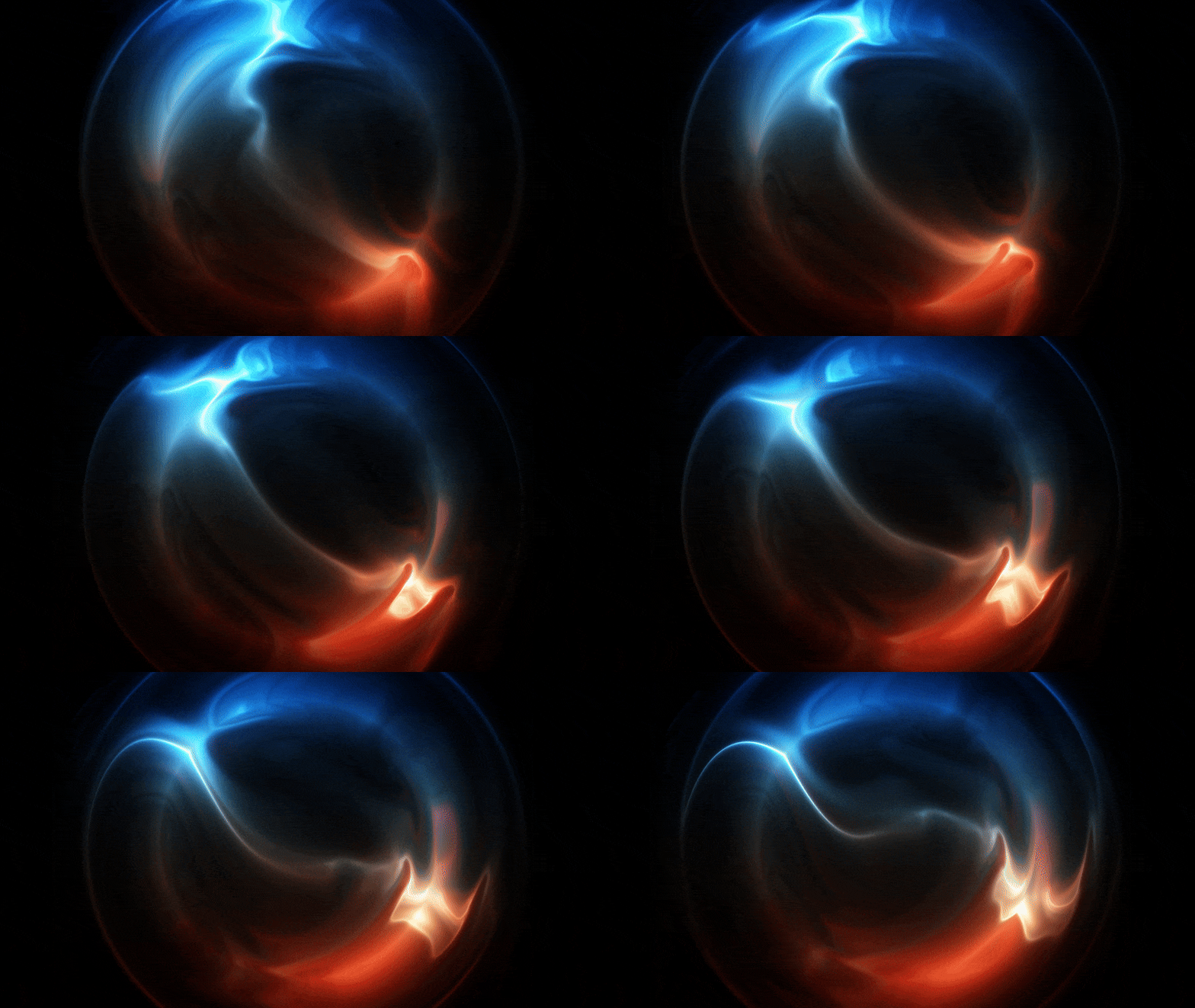 Fig. 1: The animation, rendered entirely on the CPU (downscaled GIF of the 1920 × 1080 video)
A shader is a function per pixel
A fragment shader answers one question: what colour does this pixel have? It receives the pixel’s position and a few values that are the same for every pixel, called uniforms, and returns a colour. In Xor’s shader the inputs are
- , the pixel coordinate (
gl_FragCoordin GLSL), - , the resolution of the image in pixels,
- , the time,
and the output is a colour with components between 0 and 1. These short names come from twigl, the shader playground Xor writes in. Written as math, the shader is just a function
A GPU calls this function for every pixel at the same time, on many cores in parallel. The function cannot see its neighbours and cannot remember anything from the previous frame. That restriction is what makes it so easy to parallelise, and it also makes it easy to run anywhere else. On a CPU the same thing is two nested loops, plus a third loop for the frames of the animation:
for (int i = 0; i < 240; i++) {                        // frames
    float t = ((float)i / 240) * 2 * M_PI;
    for (int y = 0; y < h; ++y)                        // rows
        for (int x = 0; x < w; ++x) {                  // pixels in a row
            vec4 o;
            vec2 FC = {(float)x, (float)y};
            /* ... the shader ... */
            fputc(o.x * 255, f);
            fputc(o.y * 255, f);
            fputc(o.z * 255, f);
        }
}
(Simplified from main in renderer.cpp.) The loops replace the GPU, fputc
replaces the screen. What is left is to find a file format simple enough to write by
hand, and to make the shader code compile as C++.
The simplest image format: PPM
PNG and JPEG compress the image, so writing them requires either a library or a lot of code. PPM, the portable pixmap format3, does not compress anything. A binary PPM file is a short text header followed by the raw pixel values:
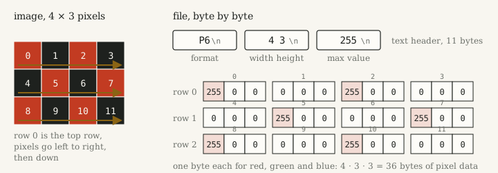 Fig. 2: A 4 × 3 image as a binary PPM file. The header says P6 (binary RGB), the width and height, and the largest value of a colour channel. Then come the pixels, row by row from the top, one byte each for red, green and blue.
With a maximum value of 255 each channel takes exactly one byte. Pixel of an image with width therefore starts at byte
Because the loop above visits the pixels in exactly this order, the renderer never has
to compute an offset. It writes the header with fprintf and then simply appends three
bytes per pixel. The first real commit of the repository did nothing else: a 960 × 540
image in which every pixel is 255 0 0, plain red.
The next commit turned the single image into an animation. A loop writes one file per frame, and each pixel decides its colour from its position and the frame number . With tiles of 60 pixels this produces a moving red and black checkerboard:
if (((y + i) / 60 + (x + i) / 60) % 2 == 0)   // integer division: tile row + tile column
    { fputc(0xFF, f); fputc(0x00, f); fputc(0x00, f); }   // red
else
    { fputc(0x00, f); fputc(0x00, f); fputc(0x00, f); }   // black
This is already a shader in everything but name: a pure function of , evaluated once per pixel. Adding to both coordinates moves the pattern one pixel up and to the left per frame.
Making C++ look like GLSL
Xor’s shader cannot be pasted into C++ as it is. GLSL has vector types like vec2 and
vec4, arithmetic on whole vectors, functions like sin and cos that work
component-wise, and swizzles: v.yx is the vector with its components swapped, and
v.xyyx builds a vec4 out of the two components of v. C++ has none of this, but
operator overloading can provide all of it. A vector is a small struct, and every
operation the shader needs becomes a one-line function:
struct vec2 {
    float x, y;
    vec2(float x = 0, float y = 0) : x(x), y(y) {}
    vec2 yx() const { return vec2(y, x); }               // swizzles as methods
    vec4 xyyx() const { return vec4(x, y, y, x); }
};

vec2 operator*(const vec2 &a, float s) { return vec2(a.x * s, a.y * s); }
vec2 operator+(const vec2 &a, const vec2 &b) { return vec2(a.x + b.x, a.y + b.y); }
float dot(const vec2 &a, const vec2 &b) { return a.x * b.x + a.y * b.y; }
vec2 cos(const vec2 &a) { return vec2(cosf(a.x), cosf(a.y)); }
vec4 tanh(const vec4 &a) { return vec4(tanhf(a.x), tanhf(a.y), tanhf(a.z), tanhf(a.w)); }
The file defines 22 of these, from vec2 * float to float - vec4: just the
operations this one shader needs, not a general vector library. The only visible difference to
GLSL is that swizzles need parentheses, v.yx() instead of v.yx. With that, the
shader goes into the pixel loop almost character for character:
vec2 p = (FC * 2. - r) / r.y, l, i, v = p * (l += 4. - 4. * abs(.7 - dot(p, p)));
for (; i.y++ < 8.; o += (sin(v.xyyx()) + 1.) * abs(v.x - v.y))
    v += cos(v.yx() * i.y + i + t) / i.y + .7;
o = tanh(5. * exp(l.x - 4. - p.y * vec4(-1, 1, 2, 0)) / o);
One detail is easy to miss. The first line declares a new vec2 called i, which
shadows the frame counter int i of the outer loop for the rest of the block. That is
harmless here, because has already been computed from the frame counter, but it
shows how literally the code was copied.
Inside Xor’s shader
Four lines of code golf are hard to read, so here is the same shader as math, one step at a time. You can follow every step for a single pixel in the demo further down.
1. Normalised coordinates. The pixel position is moved so that the image centre is at the origin and divided by the image height:
The vertical coordinate now runs from to . The horizontal one runs from to on a 16:9 image, so a circle stays round whatever the aspect ratio.
2. A ring. The variable peaks on the circle , a radius of about 0.84, and falls off linearly in on both sides:
3. Turbulence. The point is pushed around eight times by cosine waves, each one with a higher frequency and a smaller amplitude :
This technique is called domain warping. Each step distorts the result of the previous
one, which gives the swirling, fluid look. The time only shifts the phase of the
cosines, so the pattern flows without changing its character. The term is the
+ i in the code: the counter i is the vector .
4. Accumulation. After every step the shader adds up how far is from the diagonal , weighted by a sine of that differs per colour channel:
Where stays close to the diagonal, stays small. These places become the thin
bright filaments. Because the swizzle is xyyx, the green and blue sums are always
identical, and so are red and the unused fourth component. The colour differences come
almost entirely from the next step.
5. Colour and tone mapping. Finally the glow of the ring is divided by and squashed into :
is exactly 1 on the ring and decays quickly away from it. The weights
tilt the colours along the vertical axis: red grows with , blue with
, so one half of the ring glows red and the other blue. acts as a
tone mapper. Large values approach 1 smoothly instead of being clipped, so the bright
filaments do not saturate into flat white. The fourth component exists only because
o is a vec4, and it is never written to the file.
The demo runs the same shader, translated line by line into JavaScript, with the same two nested loops. It also contains the checkerboard from the second commit and a view of the normalised coordinates .
Time and the loop
The renderer writes 240 frames, and frame uses
Since appears only inside , the shader is periodic in with period . Frame 240 would be identical to frame 0, so the 240 frames loop seamlessly when the video repeats.
Each frame is a 1920 × 1080 PPM file. FFmpeg reads the numbered files as an image sequence and encodes them as an MP4:
g++ -O3 renderer.cpp -o renderer
./renderer
ffmpeg -i output/ppm/frame_%02d.ppm -r 60 output/output.mp4
Results
The rendered animation is the GIF at the top of this page. In numbers:
| resolution | 1920 × 1080 |
| frames | 240 |
| shader calls | 497,664,000 |
| iterations of the turbulence loop | 3,981,312,000 |
| size of one PPM frame | 6,220,817 bytes |
| PPM files in total | 1.49 GB |
| render time per frame | about 3.6 s |
The render time was measured on my machine with g++ 13.1 and -O3, rendering four of
the frames: 14.4 seconds, so about 14 minutes for the whole animation. On a GPU the same
shader runs in real time in a browser tab, which means at most about 17 ms per frame at
60 frames per second. That is more than 200 times faster, and it is the reason GPUs
exist. The arithmetic is the same in both cases. The CPU just does it one pixel at a
time, on one core.
Footnotes
-
Xor (@XorDev), the original shader: x.com/XorDev/status/1894123951401378051. ↩
-
Tsoding Daily, youtube.com/@Tsoding. ↩
-
Netpbm, PPM format specification, netpbm.sourceforge.net/doc/ppm.html. ↩